Prosthetic Mobility Device for a Paraplegic Cat
Independent researcher, Jack Linger Explorer Grant, 2023
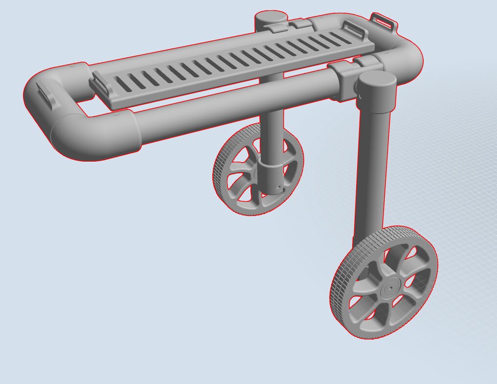
The full assembly from Onshape: polycarbonate frame, modular brackets, spinal brace, and the printed wheels. Drag to rotate, scroll to zoom.
| Role | Independent researcher |
|---|---|
| Context | Jack Linger Explorer Grant |
| Dates | 2023 |
| Field | Rehab and Mobility Tech, User-Centered Design |
| Skills | Onshape, 3D Printing, Material Selection, Expert Consultation, CAD, Grant Writing, Biomechanics |
The problem
Most mobility device design starts with a specification sheet. This one started with a job interview. Walking out of an interview at a local electronics repair shop, the owner mentioned his paraplegic F5 Savannah cat, Moo, who had lost all mobility below the waist after a spinal injury. He knew I was my robotics team’s CAD lead and asked if I would design a prosthesis. I said yes on the spot.
Moo needed a device that worked on varied terrain, accommodated a fully static lower limb with no muscle engagement, and fit the body of a large exotic breed capable of a seven-foot vertical jump. Every device the owner had tried failed on fit. Commercial options were cost-prohibitive. The pet mobility aids market was valued at roughly $1.8B in 2023 and is growing, with cats the fastest-growing segment, but the barrier is not technology. It is cost and customization.
What I built
I applied for the Jack Linger Explorer Grant, a competitive independent research award at Durham Academy, and was awarded $500. A $500 budget is a design constraint, not a footnote. The goal was a device anyone with a 3D printer could replicate, no design shop required.
- Converted Moo’s measurements into a full CAD body model in Onshape, then designed each subsystem against it
- Wheels. 3D-printed with internally bent struts for passive shock absorption, semi-flexible nylon for compliance, treaded surfaces for traction
- Frame. Modular polycarbonate tube with interchangeable brackets (4.2 to 7.2 in) so fit could be adjusted during live testing
- Spinal brace. TPU flexible print to spread load along the back
- Leg support. The hardest problem. A static limb cannot be braced with a rigid splint because there is no muscle tension to work against. After consulting a professional prosthetics designer who had hit the same failure mode in human patients, I built a hammock-style elastic cradle that suspends the limb without constraining it
- Materials: PETG for structure, TPU for the spinal support, nylon for wheels, carbon fiber filament at high-stress joints
Phase two
With remaining funds I scoped pneumatic shock absorbers to restore part of Moo’s vertical jump. That phase was designed but not built at project close.